")
")
")

")
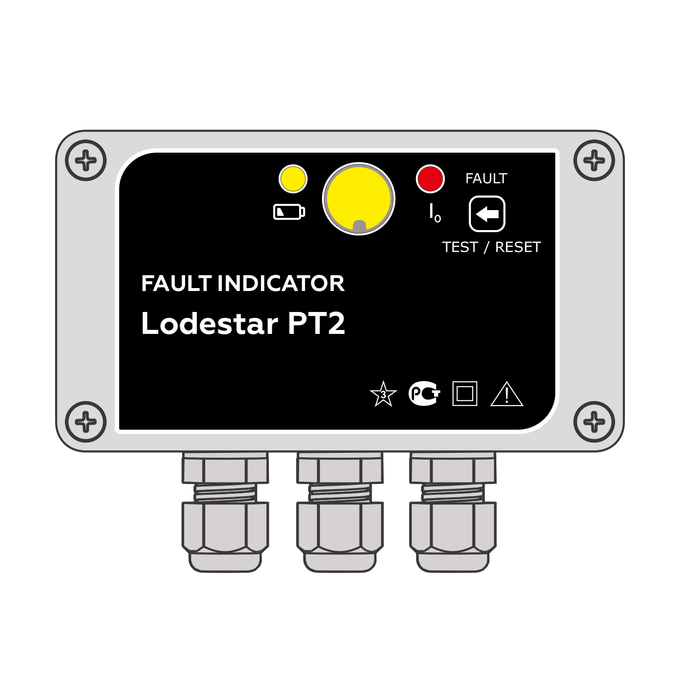
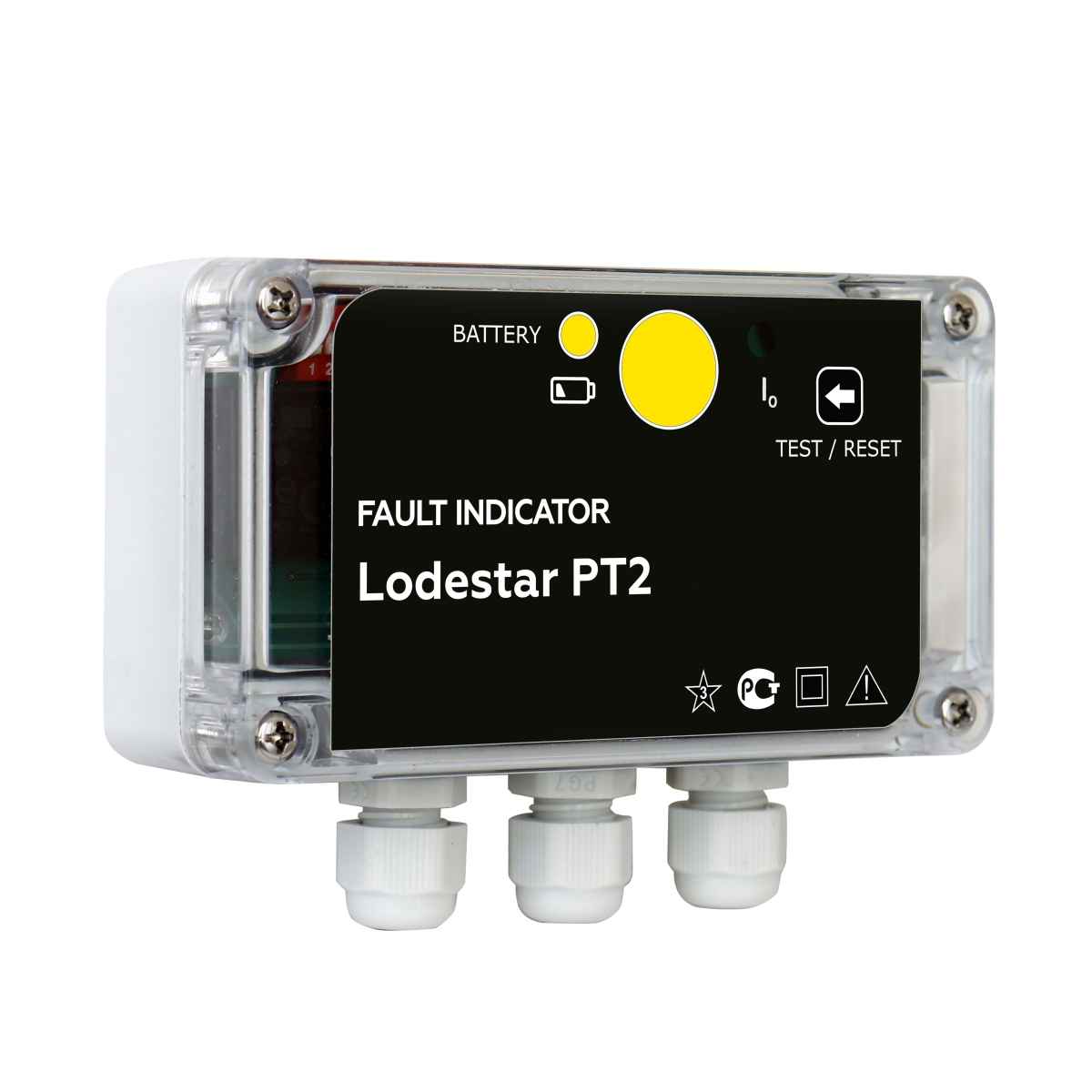
Lodestar PT2


Description
Cable fault indicator Lodestar PT2 is intended for detection of fault localization in overhead and cable power distribution lines of 6-35 kV.
The cable fault locator can operate in networks with insulated, grounded and resistance-grounded neutral types.
The fault detector is installed on control panel board of switchgear cell / wall-mounted.
Cable fault locator Lodestar PT2 benefits:
- Phase-to-Ground faults detection;
- Fault indication by switching on ultra-bright LED and mechanical flag;
- Power supply of the indicator from DC or AC source with voltage of =220V, =110V, or mains supply ~220V;
- Standby Lithium battery for backup supply of LEDs emergency indication while loss of main power;
- Changing setpoints via DIP-switch/remotely;
- Low battery level indication.
Current sensor of Lodestar PT2 is installed on the cable's armor of three phases. Indicator is installed on the control panel in the switchgear and control gear cell.
Cable fault indicator Lodestar PT2 Technical characteristics
| PARAMETER | VALUE |
| Events | |
| Types of registered faults | dentification of single-phase PtG |
| Current response threshold PtGn | from 10 A |
| General description of the Device | |
| Operating voltage | 6-35 kV |
| Indication | - Mechanical flag (blinker) - Ultra-bright LED indication |
| Power supply | - an auxiliary services supply with any type of voltage = 220 V, = 110 V or from the mains ~ 220 V - standby power supply (lithium battery) for fault indication (LEDs blinking time is more than 1200 hours) |
| Reset | - the external command on the dry contacts - time - manual button on the Device - remote |
| Trigger control | - visual - relay output |
| Mean time between failures | at least 110 000 hours |
| Additional features | changing of setpoints by DIP switch |
| Parameters | |
| PtG fault current range | 10 ÷ 200 A |
| PtG fault observation time | 60 ÷ 150 ms |
| Design | |
| Installation | On the control panel in the switchgear and control gear cell / Wall-mounted |
| Sensors | sensors based on Rogowski coil (1 pcs.) |
| Temperature range | standard from -40° ? to +75° ? |
| International Protection Marking | IP 65 |
| Impact of external climatic factors | S4 design group according to the requirements and Moderately Cold Climate design of placement category 3.1 according to IEC 721-2-1, but for operation at ambient air temperature from -40 to +75°C |
| Impact of mechanical factors | M7 design according to IEC 721-3-3-87, design group N2 according to the requirements |