")
")
")

")
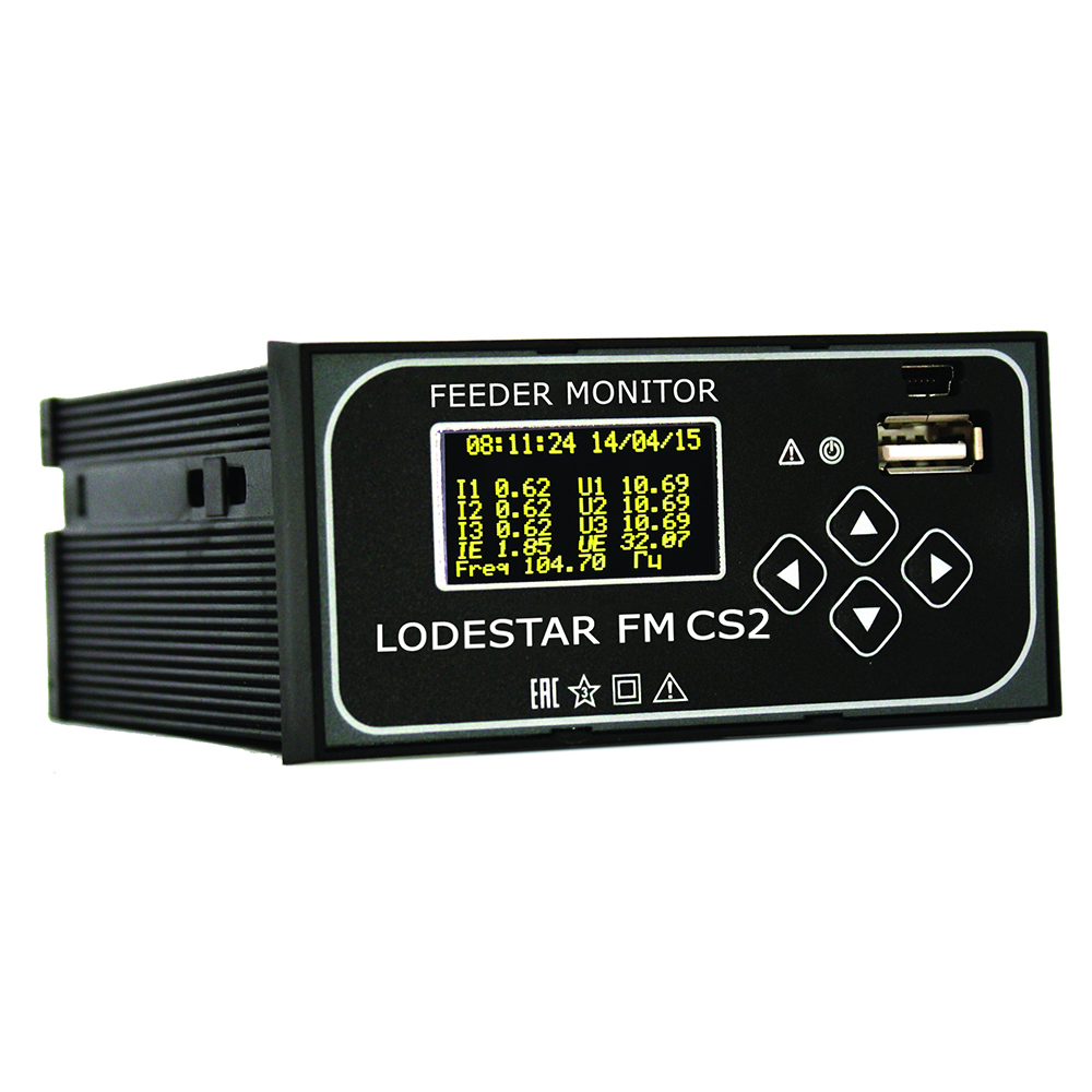
Lodestar FM-CS2
Description
Minimum dimensions – maximum functionality.
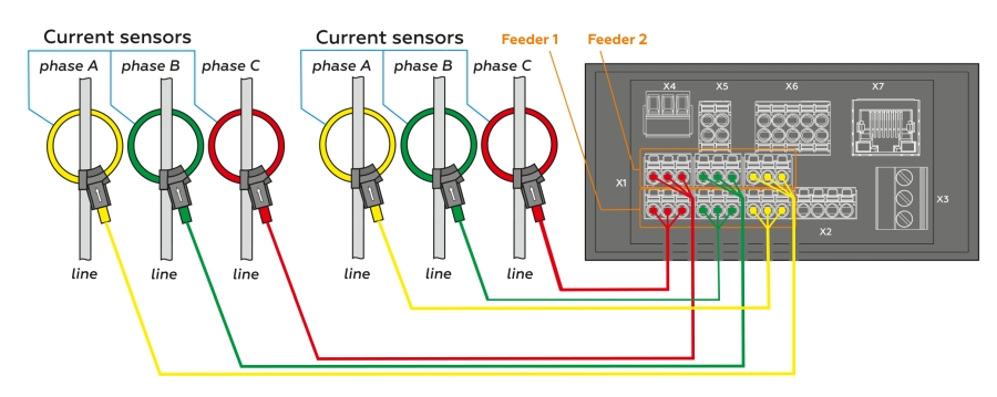
A Feeder Monitor Lodestar FM-CS2 can be used as a logger, fault current indicator, high-voltage control device. It is designed for switchgear cell with double cable output.
Lodestar FM-CS2:
- Detects fault direction
- Effective in resonant grounded neutral grid
- Logs all types of emergency situation:
- phase-to-phase faults;
- phase -to-ground faults;
- 2-or-3-phase -to-ground faults - Operates in mixed networks: overhead, cable and overhead-cable ones
- High accuracy in measurement of current and voltage
- Up to 0.1 A short-circuit faults logging
- Immediate data processing in the Device
- Operates in double-ended and loop fed networks, as well as in radial networks
- Feeder Monitor Lodestar FM-CS2 displays a faulted phase on the front LED-display
- Event information both visually and in the SCADA system
- Easy to configure by a couple of clocks in SW
- Memorizes more than 200 events
Combines the functions of selective detection of all faulted lines and main power parameters measurement.
Feeder Monitor Lodestar FM-CS2 monitors independently each input of switchgear cell with double cable input The Device in mounted in a switchgear cell or on a switchboard.
Technical characteristics of Lodestar FM-CS2
| PARAMETER | VALUE |
| Types of logged faults | - 2-and-3- phase short-circuit fault identification; - 2-and-3- phase short-circuit fault direction finding; - 2-and-3- phase-to-ground fault identification; - 2-and-3- phase-to-ground fault direction finding; - Phase-to-ground fault identification; - Phase-to-ground fault direction finding. |
| Recording the line switching faults | Yes |
| Selictivity | Phase-to-ground and short-circuit faults direction finding (PtG, PtP) |
| Determining the directions of PtG | Yes |
| Current response threshold PtG | from 0,5 A |
| Current response threshold PtP | from 10 A |
| External measuring sensor | - Rogovsky coil (6 pcs.) - Standard / capacitive divider |
| Fault visual indication | - LED-display; - LED-indication |
| Number of memorized faults | 240 |
| Power supply used in the indicator | - Inbuilt standby removable lithium storage battery (15 years); - Powered via operation current source with any type of voltage =100 – 240 V (±10%), |
| Fault indication reset | - By an external command; - By the timer; - By the device button |
| Interface | RS-485 MODBUS communication protocol Ethernet IEC104 communication protocol |
| Logging of | - Voltage; - Current; - Power; - Industrial frequency; - Power factor in three phases; - Flow distribution direction |
| Measurement accuracy | - Voltage: - when using capacitive dividers - 3%; - when using voltage transformer - 1%; - Current 3%; - Active, reactive and full power - 3%; - Industrial frequency - 1% |
| Temperature Range | standard from -50 °C to +70 °C |